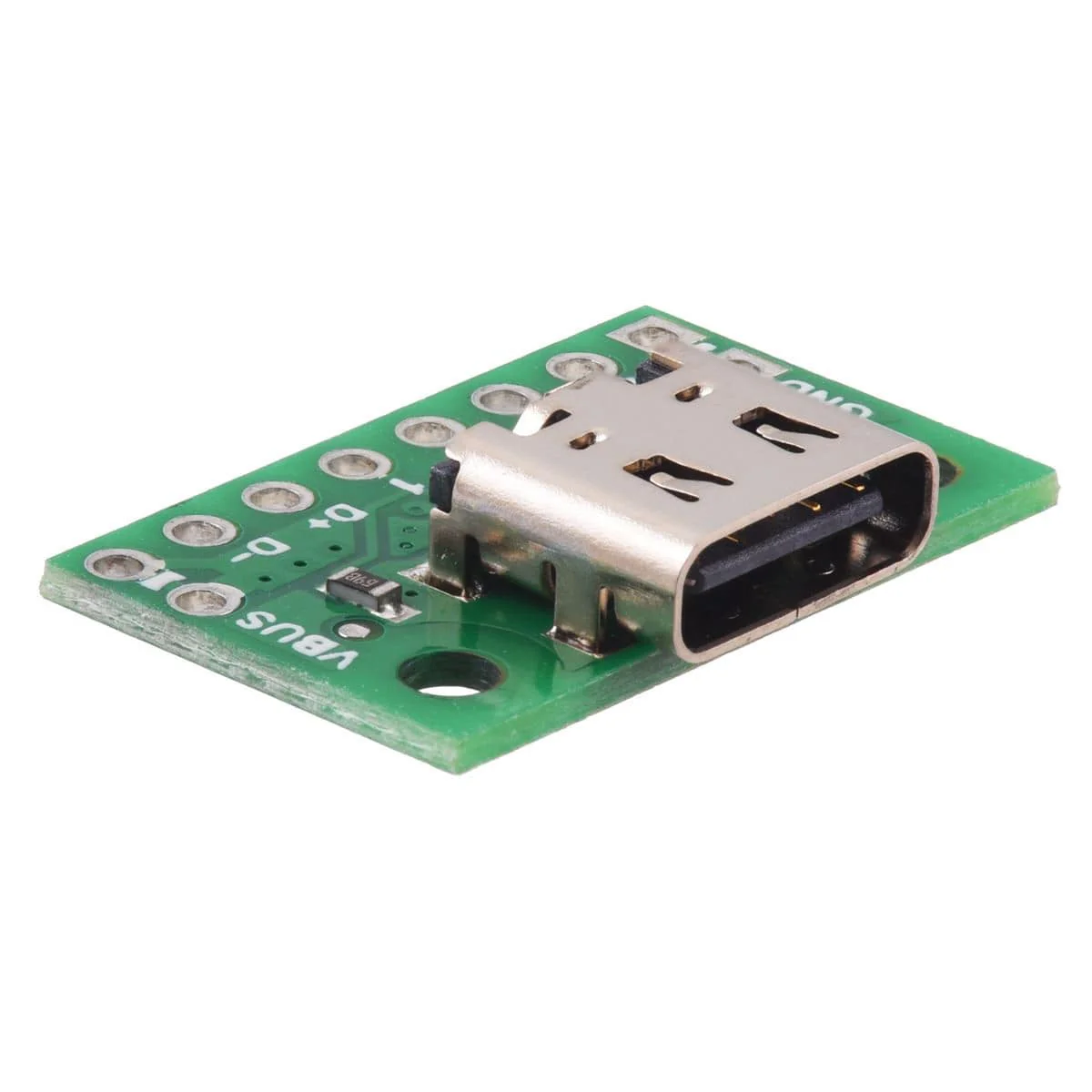
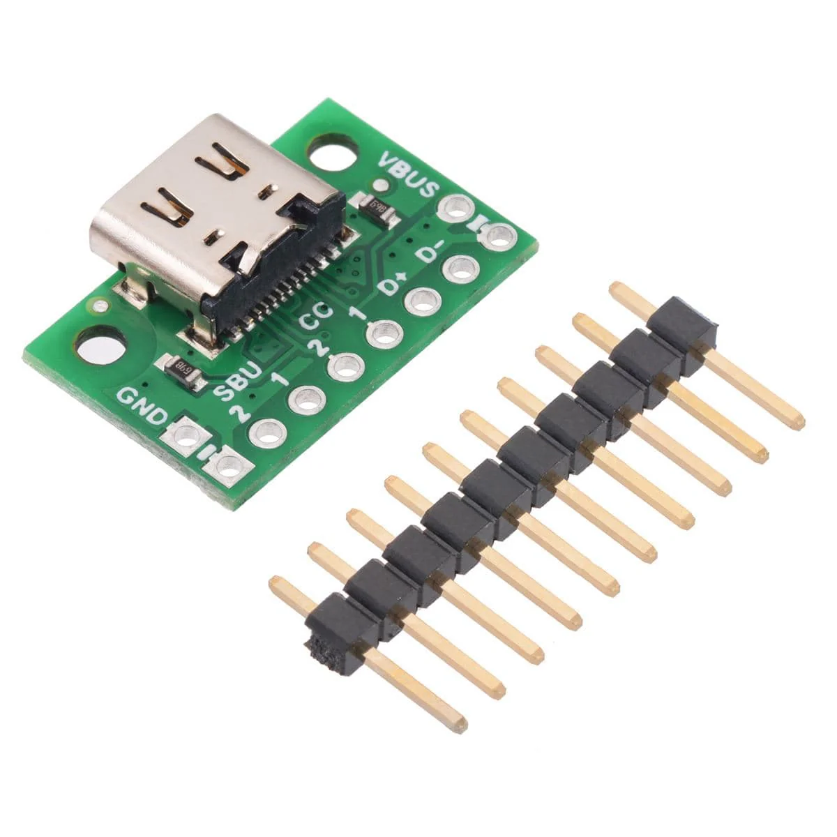
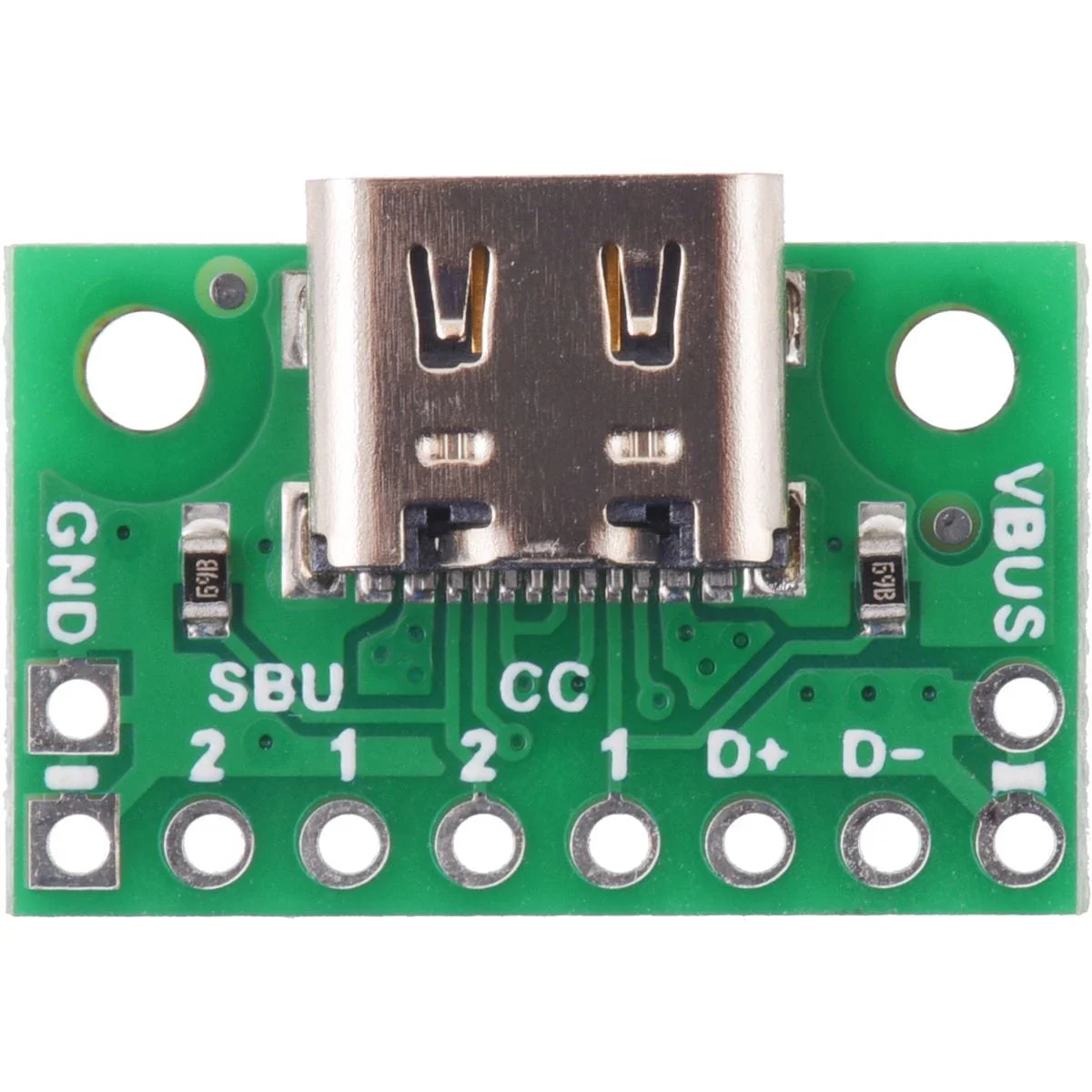
Pololu USB 2.0 Type-C Connector Breakout Board (usb07b)
This simple board breaks out the power, USB 2.0 data, configuration, and sideband pins of a USB Type-C connector to a 0.1″ spacing that is compatible with standard perfboards, solderless breadboards, and 0.1″ connectors. On-board CC pull-down resistors make it easy to use the receptacle in a power-sinking application.
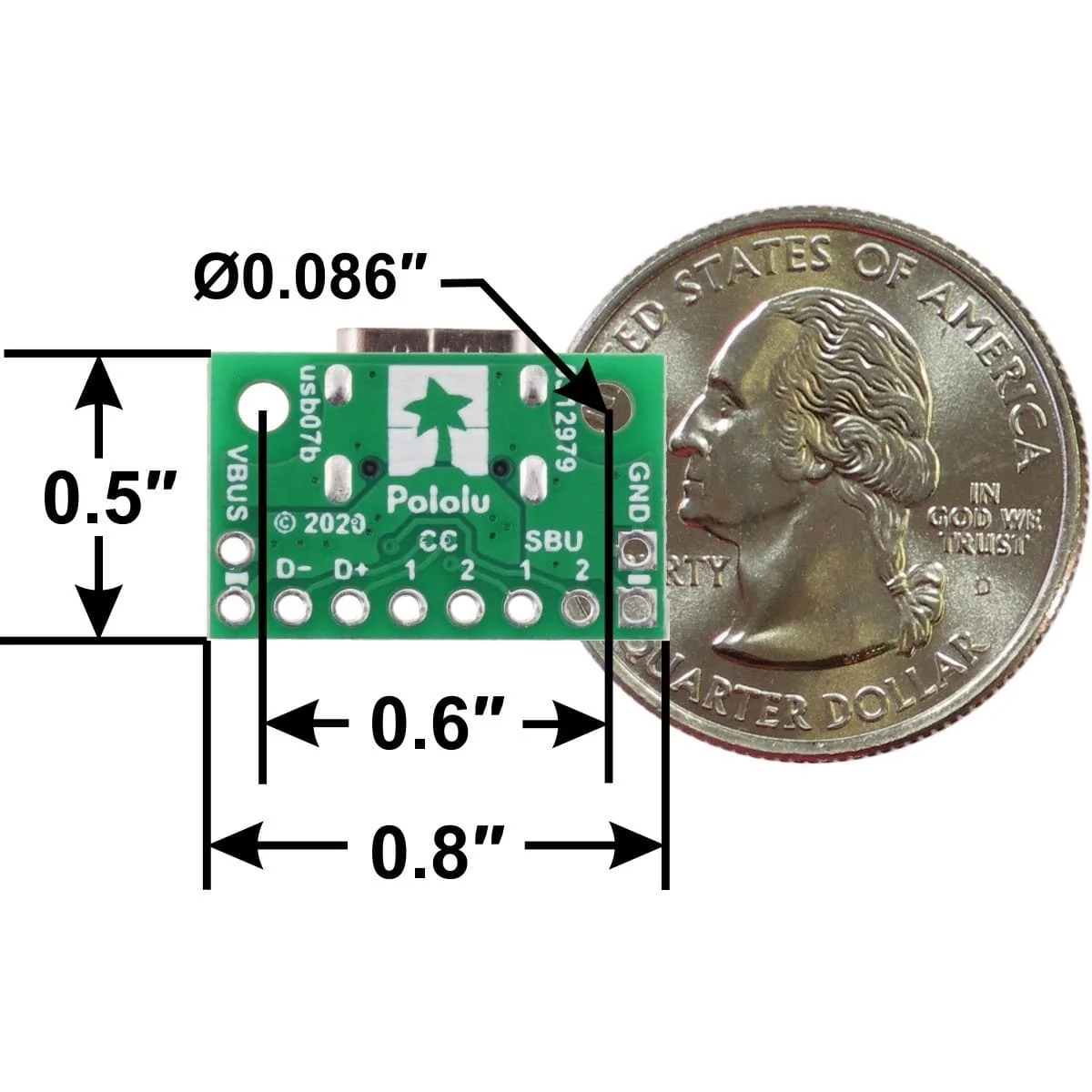
The USB-C connector’s 16 tightly-spaced pins make it difficult to use in a hobby project or prototype design. This breakout board helps by providing access to the connector’s pins for power (VBUS and GND), USB 2.0 differential data (D+ and D−), Configuration Channel (CC), and Sideband Use (SBU). Each of these pins is broken out into a 1×8 row of 0.1″-spaced pins on the board, along with duplicate VBUS and GND pins for high-current applications.
The included 1×10 straight male header can be soldered to these pins to allow the board to be used with standard perfboards, solderless breadboards, and 0.1″ connectors.
This board does not provide access to the USB 3.1 SuperSpeed differential pairs (TX and RX signals), so it only supports USB 2.0 Low-Speed, Full-Speed, and High-Speed communication.
This tiny unit measures only 0.8″ × 0.5″ (0.8″ × 0.55″ including its USB Type-C connector) and has two 0.086″ diameter mounting holes for #2 or M2 screws.
Using the breakout
Configuration and auxiliary pins
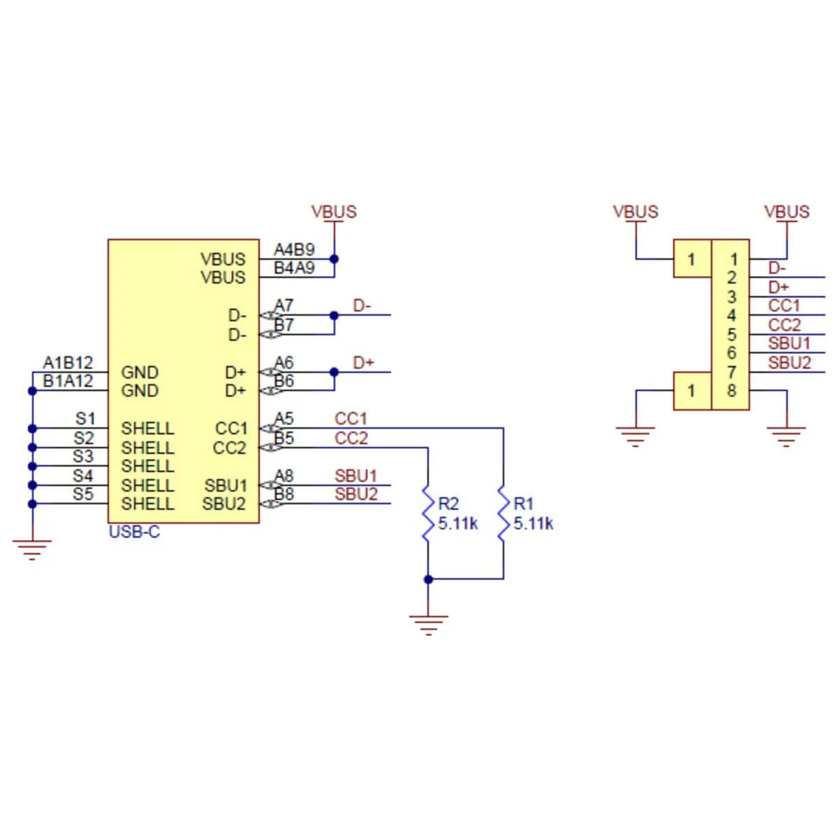
A Type-C receptacle can either provide power as a “Source” or consume power as a “Sink”; this usually corresponds to whether the port is a USB host (Downstream Facing Port, or DFP) or USB device (Upstream Facing Port, or UFP). The Configuration Channel, or CC, pins are used to determine the role of a port when it is connected.
This carrier board pulls the CC1 and CC2 pins to GND through 5.11 kΩ termination resistors, making the port a Sink and a UFP by default and allowing it to be a straightforward replacement for a Type-B, Mini-B, or Micro-B port on a USB device. If you want the port to serve as a Source instead, or if you want to perform more advanced configuration like USB Power Delivery negotiation, you can disconnect or remove the onboard resistors and make your own connections to the CC pins exposed by the board.
The Sideband Use, or SBU, pins are not used by the USB protocol. Instead, they are available for use after the USB interface has been configured to operate in an Alternate Mode, which allows it to be repurposed for other protocols and applications. This configuration is done through communication on the CC line between the host and device using the USB Power Delivery protocol.
Resources
- Schematic
- Dimensions
- 3D Model
- Drill Guide DXF
Product Information
Product Information
Shipping & Returns
Shipping & Returns
Pololu USB 2.0 Type-C Connector Breakout Board (usb07b)
Pololu USB 2.0 Type-C Connector Breakout Board (usb07b)
This simple board breaks out the power, USB 2.0 data, configuration, and sideband pins of a USB Type-C connector to a 0.1″ spacing that is compatible with standard perfboards, solderless breadboards, and 0.1″ connectors. On-board CC pull-down resistors make it easy to use the receptacle in a power-sinking application.
The USB-C connector’s 16 tightly-spaced pins make it difficult to use in a hobby project or prototype design. This breakout board helps by providing access to the connector’s pins for power (VBUS and GND), USB 2.0 differential data (D+ and D−), Configuration Channel (CC), and Sideband Use (SBU). Each of these pins is broken out into a 1×8 row of 0.1″-spaced pins on the board, along with duplicate VBUS and GND pins for high-current applications.
The included 1×10 straight male header can be soldered to these pins to allow the board to be used with standard perfboards, solderless breadboards, and 0.1″ connectors.
This board does not provide access to the USB 3.1 SuperSpeed differential pairs (TX and RX signals), so it only supports USB 2.0 Low-Speed, Full-Speed, and High-Speed communication.
This tiny unit measures only 0.8″ × 0.5″ (0.8″ × 0.55″ including its USB Type-C connector) and has two 0.086″ diameter mounting holes for #2 or M2 screws.
Using the breakout
Configuration and auxiliary pins
A Type-C receptacle can either provide power as a “Source” or consume power as a “Sink”; this usually corresponds to whether the port is a USB host (Downstream Facing Port, or DFP) or USB device (Upstream Facing Port, or UFP). The Configuration Channel, or CC, pins are used to determine the role of a port when it is connected.
This carrier board pulls the CC1 and CC2 pins to GND through 5.11 kΩ termination resistors, making the port a Sink and a UFP by default and allowing it to be a straightforward replacement for a Type-B, Mini-B, or Micro-B port on a USB device. If you want the port to serve as a Source instead, or if you want to perform more advanced configuration like USB Power Delivery negotiation, you can disconnect or remove the onboard resistors and make your own connections to the CC pins exposed by the board.
The Sideband Use, or SBU, pins are not used by the USB protocol. Instead, they are available for use after the USB interface has been configured to operate in an Alternate Mode, which allows it to be repurposed for other protocols and applications. This configuration is done through communication on the CC line between the host and device using the USB Power Delivery protocol.
Resources
- Schematic
- Dimensions
- 3D Model
- Drill Guide DXF
Original: $5.17
-70%$5.17
$1.55Product Information
Product Information
Shipping & Returns
Shipping & Returns
Description
This simple board breaks out the power, USB 2.0 data, configuration, and sideband pins of a USB Type-C connector to a 0.1″ spacing that is compatible with standard perfboards, solderless breadboards, and 0.1″ connectors. On-board CC pull-down resistors make it easy to use the receptacle in a power-sinking application.
The USB-C connector’s 16 tightly-spaced pins make it difficult to use in a hobby project or prototype design. This breakout board helps by providing access to the connector’s pins for power (VBUS and GND), USB 2.0 differential data (D+ and D−), Configuration Channel (CC), and Sideband Use (SBU). Each of these pins is broken out into a 1×8 row of 0.1″-spaced pins on the board, along with duplicate VBUS and GND pins for high-current applications.
The included 1×10 straight male header can be soldered to these pins to allow the board to be used with standard perfboards, solderless breadboards, and 0.1″ connectors.
This board does not provide access to the USB 3.1 SuperSpeed differential pairs (TX and RX signals), so it only supports USB 2.0 Low-Speed, Full-Speed, and High-Speed communication.
This tiny unit measures only 0.8″ × 0.5″ (0.8″ × 0.55″ including its USB Type-C connector) and has two 0.086″ diameter mounting holes for #2 or M2 screws.
Using the breakout
Configuration and auxiliary pins
A Type-C receptacle can either provide power as a “Source” or consume power as a “Sink”; this usually corresponds to whether the port is a USB host (Downstream Facing Port, or DFP) or USB device (Upstream Facing Port, or UFP). The Configuration Channel, or CC, pins are used to determine the role of a port when it is connected.
This carrier board pulls the CC1 and CC2 pins to GND through 5.11 kΩ termination resistors, making the port a Sink and a UFP by default and allowing it to be a straightforward replacement for a Type-B, Mini-B, or Micro-B port on a USB device. If you want the port to serve as a Source instead, or if you want to perform more advanced configuration like USB Power Delivery negotiation, you can disconnect or remove the onboard resistors and make your own connections to the CC pins exposed by the board.
The Sideband Use, or SBU, pins are not used by the USB protocol. Instead, they are available for use after the USB interface has been configured to operate in an Alternate Mode, which allows it to be repurposed for other protocols and applications. This configuration is done through communication on the CC line between the host and device using the USB Power Delivery protocol.
Resources
- Schematic
- Dimensions
- 3D Model
- Drill Guide DXF